2 Answers
1. **Components**:
- **Resistor (R)**: Opposes current flow, causing a voltage drop proportional to the current (Ohm’s Law: \( V = IR \)).
- **Inductor (L)**: Stores energy in a magnetic field when current flows through it and opposes changes in current (Voltage across an inductor: \( V_L = L \frac{dI}{dt} \)).
- **Capacitor (C)**: Stores energy in an electric field and opposes changes in voltage (Current through a capacitor: \( I_C = C \frac{dV}{dt} \)).
2. **Types of RLC Circuits**:
- **Series RLC Circuit**: All components are connected in a single path. The total impedance \( Z \) is given by \( Z = R + j\left(\omega L - \frac{1}{\omega C}\right) \), where \( j \) is the imaginary unit and \( \omega \) is the angular frequency of the source.
- **Parallel RLC Circuit**: Components are connected in parallel. The total impedance is found by combining the admittances of the components: \( Y = \frac{1}{R} + \frac{1}{j \omega L} + j \omega C \).
3. **Analysis Techniques**:
- **Phasor Analysis**: Useful for solving AC circuits by converting differential equations into algebraic ones using complex numbers.
- **Impedance and Admittance**: Impedance (Z) is used for series circuits, while admittance (Y) is used for parallel circuits. Both concepts help in simplifying circuit analysis.
- **Transient Analysis**: For analyzing how circuits respond to changes in voltage or current, typically using differential equations.
4. **Applications**:
- **Filters**: RLC circuits are used in designing low-pass, high-pass, band-pass, and band-stop filters.
- **Oscillators**: They can generate oscillatory signals based on the resonance frequency.
- **Tuning Circuits**: Used in radios and televisions to select specific frequencies.
Would you like more details on a specific aspect of RLC circuit analysis?
### Components and Their Behavior
1. **Resistor (R)**:
- **Function**: Provides resistance to the flow of electric current, causing a voltage drop proportional to the current (Ohm's Law: \( V = IR \)).
- **Impedance**: In the frequency domain, the impedance of a resistor is \( R \), which is constant regardless of frequency.
2. **Inductor (L)**:
- **Function**: Stores energy in its magnetic field when current flows through it. It resists changes in current.
- **Impedance**: In the frequency domain, the impedance of an inductor is \( j\omega L \), where \( \omega \) is the angular frequency (\( \omega = 2\pi f \)), and \( j \) is the imaginary unit.
3. **Capacitor (C)**:
- **Function**: Stores energy in its electric field when a voltage is applied across it. It resists changes in voltage.
- **Impedance**: In the frequency domain, the impedance of a capacitor is \( \frac{1}{j\omega C} \).
### Types of RLC Circuits
1. **Series RLC Circuit**:
- **Configuration**: Resistor, inductor, and capacitor are connected in a single series loop.
- **Total Impedance**: \( Z_{total} = R + j\omega L + \frac{1}{j\omega C} \).
- **Resonance**: The circuit can resonate at a frequency where the inductive reactance equals the capacitive reactance (\( \omega L = \frac{1}{\omega C} \)), leading to maximum current flow and minimum impedance.
2. **Parallel RLC Circuit**:
- **Configuration**: Resistor, inductor, and capacitor are connected in parallel.
- **Total Impedance**: The total impedance \( Z_{total} \) is found using the reciprocal formula for parallel impedances:
\[
\frac{1}{Z_{total}} = \frac{1}{R} + \frac{1}{j\omega L} + j\omega C
\]
- **Resonance**: Similar to the series circuit, resonance occurs when the reactive components cancel each other out.
### Analysis Techniques
1. **Phasor Analysis**:
- Used for AC circuits to simplify the analysis by converting time-domain sinusoidal voltages and currents into frequency-domain phasors.
- Impedance is used to analyze the circuit using Ohm's Law and Kirchhoff's Laws.
2. **Frequency Response**:
- Analyzing how the circuit responds to different frequencies.
- **Bode Plots**: Graphical representations of the magnitude and phase of the circuit’s frequency response.
3. **Transient Analysis**:
- Examines how the circuit responds over time when a sudden change (like a step function) is applied.
- Solves differential equations describing the circuit’s behavior.
4. **Laplace Transform**:
- A mathematical technique used to transform the time-domain circuit equations into the s-domain, simplifying the analysis of circuits with complex waveforms and initial conditions.
### Practical Applications
- **Filters**: RLC circuits are used to create filters that can pass or block specific frequencies. For example, low-pass, high-pass, band-pass, and band-stop filters.
- **Oscillators**: Used in radio and television transmitters to generate oscillations at specific frequencies.
- **Tuning Circuits**: Used in radios and other communication devices to select the desired frequency from a range of frequencies.
By understanding these principles and techniques, you can analyze and design circuits that effectively utilize the interactions between resistors, inductors, and capacitors.

Applied Physics
Signals and Systems

Digital Electronics
Basic Concepts
Basic Laws
Units
Ohmic Resistors
Capacitors and Inductors
RC Circuit
First-Order Circuits
Second-Order Circuits
Principles Of Circuit Analysis
Sinusoids and Phasors
AC Steady-State Analysis
Single Phase A.C. Circuits
Three-Phase Circuits
Resonance In Series And Parallel Circuits
Network Theorems
Thevenin's Theorem
Two-port Networks
Digital Electronics
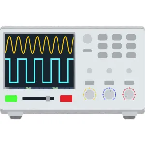
Oscilloscope
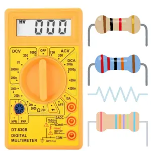
Ohmmeter
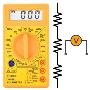
Voltmeter
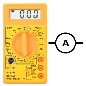
Ammeter
Induction Motor
Transformer
Operational Amplifiers
Components
Symbols
Formulas
EE Notes
EE Dictionary

MCQ Quiz

Interview Q&A
Power Electronics Book
Advanced Calculator
Basic Calculator
Simulator
Videos
Q&A
Capacitance Meter
Two Way Switch
Electrical Machines
Power Electronics

Electrical Drives & Their Control
Electrical Safety & Standards

Basics of Electronics Engineering
Electromagnetic Fields
Electrical Machines

More Items Coming Soon...