2 Answers
1. **Output Voltage (V_out)**:
\[
V_{\text{out}} = D \cdot V_{\text{in}}
\]
where \( D \) is the duty cycle (the fraction of the switching period the switch is on) and \( V_{\text{in}} \) is the input voltage.
2. **Duty Cycle (D)**:
\[
D = \frac{V_{\text{out}}}{V_{\text{in}}}
\]
This is valid for ideal converters.
3. **Inductor Current (I_L)**:
The inductor current changes during the switching cycle:
\[
\Delta I_L = \frac{V_{\text{L}} \cdot D \cdot T}{L}
\]
where \( V_{\text{L}} \) is the inductor voltage during the "on" period, \( T \) is the total period, and \( L \) is the inductance.
4. **Average Output Current (I_out)**:
The output current can be approximated as:
\[
I_{\text{out}} = I_{\text{in}} \cdot D
\]
where \( I_{\text{in}} \) is the input current.
5. **Efficiency (η)**:
The efficiency can be expressed as:
\[
\eta = \frac{P_{\text{out}}}{P_{\text{in}}} \times 100\%
\]
where \( P_{\text{out}} = V_{\text{out}} \cdot I_{\text{out}} \) and \( P_{\text{in}} = V_{\text{in}} \cdot I_{\text{in}} \).
These equations form the foundation of understanding how a buck converter operates. For practical designs, additional factors like inductor resistance, switch losses, and diode forward voltage drop should also be considered.
1. **Voltage Conversion Ratio:**
The fundamental equation for a buck converter is derived from its voltage conversion ratio. The output voltage \( V_{out} \) is related to the input voltage \( V_{in} \) and the duty cycle \( D \) of the switching element. The duty cycle is defined as the fraction of the switching period during which the switch is closed.
\[
V_{out} = D \cdot V_{in}
\]
where:
- \( V_{out} \) is the output voltage.
- \( V_{in} \) is the input voltage.
- \( D \) is the duty cycle of the switch (0 ≤ D ≤ 1).
2. **Inductor Current Ripple:**
The inductor current ripple \( \Delta I_L \) depends on the input voltage \( V_{in} \), the output voltage \( V_{out} \), the inductor \( L \), and the switching frequency \( f_s \). The ripple can be calculated using:
\[
\Delta I_L = \frac{V_{in} - V_{out}}{L \cdot f_s} \cdot D
\]
where:
- \( \Delta I_L \) is the peak-to-peak ripple current in the inductor.
- \( f_s \) is the switching frequency of the converter.
3. **Output Voltage Ripple:**
The output voltage ripple \( \Delta V_{out} \) is affected by the output capacitor \( C \), the inductor ripple current \( \Delta I_L \), and the switching frequency \( f_s \). It can be approximated by:
\[
\Delta V_{out} = \frac{\Delta I_L}{8 \cdot C \cdot f_s}
\]
where:
- \( \Delta V_{out} \) is the peak-to-peak voltage ripple at the output.
- \( C \) is the output capacitor value.
4. **Inductor Selection:**
The inductor value \( L \) is chosen based on the desired ripple current \( \Delta I_L \), the input and output voltages, and the switching frequency. A typical formula to determine \( L \) is:
\[
L = \frac{V_{out} \cdot (1 - D)}{\Delta I_L \cdot f_s}
\]
5. **Capacitor Selection:**
The output capacitor \( C \) is selected based on the acceptable voltage ripple and the ripple current. A basic formula to calculate \( C \) is:
\[
C = \frac{\Delta I_L}{8 \cdot \Delta V_{out} \cdot f_s}
\]
6. **Power Dissipation:**
The power dissipated in the components (such as the switch and inductor) affects the efficiency of the converter. The power loss in the switch and inductor needs to be minimized for better performance. Efficiency \( \eta \) is typically given by:
\[
\eta = \frac{P_{out}}{P_{in}} \times 100\%
\]
where \( P_{out} \) is the output power and \( P_{in} \) is the input power.
These equations are based on ideal conditions. In practice, additional factors such as component tolerances, parasitic elements, and non-ideal switching behavior may affect the performance of the buck converter.

Applied Physics
Signals and Systems

Digital Electronics
Basic Concepts
Basic Laws
Units
Ohmic Resistors
Capacitors and Inductors
RC Circuit
First-Order Circuits
Second-Order Circuits
Principles Of Circuit Analysis
Sinusoids and Phasors
AC Steady-State Analysis
Single Phase A.C. Circuits
Three-Phase Circuits
Resonance In Series And Parallel Circuits
Network Theorems
Thevenin's Theorem
Two-port Networks
Digital Electronics
Oscilloscope
Ohmmeter
Voltmeter
Ammeter
Induction Motor
Transformer
Operational Amplifiers
Components
Symbols
Formulas
EE Notes
EE Dictionary
MCQ Quiz

Interview Q&A
Power Electronics Book
Advanced Calculator
Basic Calculator
Simulator
Videos
Q&A
Capacitance Meter
Two Way Switch
Electrical Machines
Power Electronics
Electrical Drives & Their Control
Electrical Safety & Standards
Basics of Electronics Engineering
Electromagnetic Fields
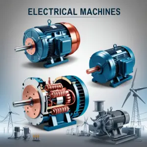
Electrical Machines

More Items Coming Soon...