2 Answers
### 1. **Efficient Energy Transfer**
- **Minimizing Losses:** Transmission lines are designed to minimize energy losses as electricity travels over long distances. These losses can occur due to resistance in the conductors, which converts electrical energy into heat. Transmission lines are typically made of materials with low resistance, such as aluminum or copper, and are designed to operate at high voltages to reduce current and, consequently, resistive losses.
- **High Voltage Operation:** By using high voltages, transmission lines reduce the amount of current needed to transfer the same amount of power. Since power loss due to resistance is proportional to the square of the current (P = I²R), reducing the current helps in minimizing these losses.
### 2. **Voltage Regulation**
- **Maintaining Voltage Levels:** Transmission lines help in maintaining voltage levels across different parts of the power grid. Voltage regulation is important to ensure that electrical equipment operates efficiently and safely. High-voltage transmission lines help in keeping voltage levels stable across large distances.
### 3. **System Reliability and Stability**
- **Grid Connectivity:** Transmission lines connect various parts of the electrical grid, allowing for the distribution of power from generating stations to substations and ultimately to end users. This connectivity helps in balancing supply and demand across different regions and enhances the reliability of the power supply.
- **Load Balancing:** They help in managing the electrical load by distributing it across different paths. This means if one part of the grid experiences high demand or failure, other parts can compensate, thus ensuring continuity of power supply.
### 4. **Flexibility and Expansion**
- **Supporting Growth:** Transmission lines allow for the expansion and development of electrical grids. As demand for electricity grows or new power sources (like renewable energy plants) are added, transmission lines can be expanded or upgraded to meet new requirements.
- **Integration of Renewable Energy:** They play a crucial role in integrating renewable energy sources like wind and solar power into the grid. These energy sources are often located far from where the electricity is needed, and transmission lines help in transporting this energy efficiently.
### 5. **Signal Transmission**
- **Communication Lines:** In addition to power transmission, specialized transmission lines are used in telecommunications and data transfer. These include coaxial cables, fiber optics, and twisted pair cables, which transmit signals with minimal interference and loss.
### Summary
Overall, the purpose of a transmission line is to ensure that electrical energy is delivered efficiently, reliably, and safely over long distances, supporting the functioning of modern power grids and enabling the distribution of electricity to homes, businesses, and industries.
### 1. **Basic Configuration**
The cascode amplifier typically consists of two stages:
- **Common-Source Stage**: This is the first stage, which is similar to a standard common-source amplifier.
- **Common-Gate Stage**: This is the second stage, which is stacked on top of the common-source stage.
Here’s a simplified circuit diagram:
```
Vdd
|
|
Rc
|
|----> Output
|
|
Q2
|
|----> Vout
|
|
Q1
|
|
Rs
|
|
GND
```
In this diagram:
- **Q1** and **Q2** are typically FETs (Field-Effect Transistors).
- **Rc** is the load resistor for Q2.
- **Rs** is the source resistor for Q1.
### 2. **Operation**
- **First Stage (Common-Source Stage)**: The signal is applied to the gate of Q1. This stage provides the initial amplification of the input signal. The source of Q1 is connected to a resistor (Rs), which helps to set the operating point and stabilize the biasing.
- **Second Stage (Common-Gate Stage)**: The output of Q1 is fed to the gate of Q2. In this stage, Q2 is configured in a common-gate configuration. This means that the gate of Q2 is connected to a constant voltage (usually through a biasing network), while the source is connected to the drain of Q1. This stage provides further amplification and increases the overall gain of the amplifier.
### 3. **Advantages**
1. **Increased Gain**: The cascode configuration provides higher gain compared to a single common-source stage because the second stage (common-gate) helps to boost the gain.
2. **Improved Bandwidth**: The cascode design can increase the bandwidth of the amplifier. This is because the output impedance of the first stage is higher when the second stage is used to buffer the output.
3. **Reduced Miller Effect**: The Miller effect is a phenomenon where the input capacitance of an amplifier stage gets amplified due to the gain of the stage. In a cascode amplifier, the Miller effect is minimized because the second stage buffers the first stage, effectively reducing the capacitance seen by the first stage.
4. **Better Stability**: The cascode configuration enhances the stability of the amplifier. By reducing the dependence of the gain on the transistor parameters, the overall amplifier becomes more predictable and less sensitive to variations.
### 4. **Example Applications**
- **RF Amplifiers**: Cascode amplifiers are widely used in RF (radio frequency) applications due to their high gain and bandwidth.
- **Operational Amplifiers**: They are used in the design of operational amplifiers (op-amps) to achieve better performance characteristics.
### 5. **Circuit Design Considerations**
- **Biasing**: Proper biasing is crucial to ensure that both transistors are operating in their active regions and to achieve optimal performance.
- **Matching Transistors**: For best performance, the transistors used in the cascode configuration should be matched to ensure symmetry and minimize distortion.
In summary, the cascode amplifier configuration is a versatile and effective design that enhances the performance of amplifiers, especially in applications where high gain and stability are critical.

Applied Physics
Signals and Systems

Digital Electronics
Basic Concepts
Basic Laws
Units
Ohmic Resistors
Capacitors and Inductors
RC Circuit
First-Order Circuits
Second-Order Circuits
Principles Of Circuit Analysis
Sinusoids and Phasors
AC Steady-State Analysis
Single Phase A.C. Circuits
Three-Phase Circuits
Resonance In Series And Parallel Circuits
Network Theorems
Thevenin's Theorem
Two-port Networks
Digital Electronics
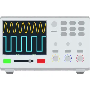
Oscilloscope
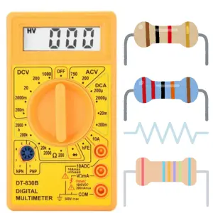
Ohmmeter
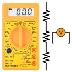
Voltmeter
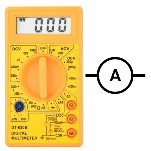
Ammeter
Induction Motor
Transformer
Operational Amplifiers
Components
Symbols
Formulas
EE Notes
EE Dictionary

MCQ Quiz

Interview Q&A
Power Electronics Book
Advanced Calculator

Basic Calculator
Simulator
Videos
Q&A

Capacitance Meter
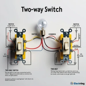
Two Way Switch
Electrical Machines
Power Electronics

Electrical Drives & Their Control

Electrical Safety & Standards

Basics of Electronics Engineering
Electromagnetic Fields
Electrical Machines

More Items Coming Soon...