2 Answers
### Overview of Three-Phase Rectification
In a three-phase system, there are three alternating currents, each 120 degrees out of phase with each other. This configuration allows for a smoother and more efficient rectification process compared to single-phase systems.
### Components of a Three-Phase Rectifier
1. **Diodes or Thyristors**: These semiconductor devices are the main components that allow current to flow in one direction. A three-phase rectifier typically uses six diodes in a bridge configuration, although it can also use thyristors for controlled rectification.
2. **Transformer** (optional): Often, a transformer is used to step down the voltage or to isolate the rectifier from the power supply.
3. **Smoothing Capacitor** (optional): This component is used to smooth out the output DC voltage by reducing ripple, which is the fluctuation in voltage levels.
### Working Principle
#### 1. **Phase Voltage and Current**:
In a three-phase system, the voltages can be represented as:
- \( V_a(t) = V_m \sin(\omega t) \)
- \( V_b(t) = V_m \sin(\omega t - 120^\circ) \)
- \( V_c(t) = V_m \sin(\omega t - 240^\circ) \)
Where \( V_m \) is the peak voltage and \( \omega \) is the angular frequency. Each phase reaches its peak voltage at different times, which helps ensure that at least one diode is conducting at any given moment.
#### 2. **Rectification Process**:
During the rectification process, the diodes conduct in a sequence, allowing current to flow only during the positive half-cycles of the AC waveform.
- **Conduction Sequence**: As the AC waveform cycles, each diode conducts when its corresponding phase voltage is higher than the others. In a typical six-pulse three-phase rectifier:
- For the first 60 degrees, diodes connected to phases A and B conduct.
- For the next 60 degrees, diodes connected to phases B and C conduct.
- For the next 60 degrees, diodes connected to phases C and A conduct.
This continuous conduction leads to a more constant output voltage.
#### 3. **Output Voltage**:
The output of a three-phase rectifier can be approximated as a series of pulses corresponding to the conduction of the diodes. The output voltage waveform looks like a series of peaks, which can be calculated using the formula:
\[
V_{DC} = \frac{3 \sqrt{3}}{\pi} V_m
\]
Where \( V_{DC} \) is the average output voltage and \( V_m \) is the maximum phase voltage.
### 4. **Filtering the Output**:
After rectification, the output is not pure DC but rather pulsating DC. To smooth this output, a filtering capacitor may be used. The capacitor charges during the peaks and discharges during the troughs, reducing the ripple and producing a more stable DC voltage.
### Advantages of Three-Phase Rectifiers
1. **Higher Average Output Voltage**: Compared to single-phase rectifiers, three-phase rectifiers provide a higher average DC output voltage.
2. **Reduced Ripple**: The output voltage ripple is lower, making it easier to filter and resulting in a more stable DC supply.
3. **Higher Efficiency**: Three-phase systems generally have higher efficiency due to better utilization of the input current.
4. **Smaller Components**: The need for smaller filtering capacitors and inductors due to reduced ripple means that overall system size can be minimized.
### Conclusion
A three-phase rectifier effectively converts AC to DC by utilizing diodes to allow current flow only during the positive cycles of the AC waveform. By leveraging the continuous nature of three-phase currents, the rectifier produces a more stable and higher voltage DC output, which is ideal for various applications in electrical engineering. This process is essential for powering electronic devices and converting electrical energy for various industrial applications.
### 1. **Three-Phase AC System Overview**
In a three-phase AC system, there are three separate AC voltage sources, each phase shifted by 120 degrees from the others. This configuration provides a more continuous and stable power supply compared to single-phase systems. The voltages can be represented as:
- Phase A: \( V_A(t) = V_{m} \sin(\omega t) \)
- Phase B: \( V_B(t) = V_{m} \sin(\omega t - 120^\circ) \)
- Phase C: \( V_C(t) = V_{m} \sin(\omega t + 120^\circ) \)
where \( V_{m} \) is the peak voltage, \( \omega \) is the angular frequency, and \( t \) is time.
### 2. **Rectifier Diode Arrangement**
In a three-phase rectifier, six diodes are typically used, arranged in a bridge configuration. This configuration is called a **three-phase bridge rectifier**. The diodes are arranged in two sets:
- **Positive Diodes:** Two diodes conduct to supply current to the positive output.
- **Negative Diodes:** Two diodes conduct to supply current to the negative output.
### 3. **Operation of the Rectifier**
The three-phase rectifier works by allowing current to flow through the load in one direction only, regardless of the AC input. Here's how it achieves this:
1. **Selection of Conducting Diodes:**
- In any given instant, only two of the six diodes conduct. Each pair of diodes conducts based on which phase voltage is the highest. The rectifier circuit automatically selects the pair of diodes that have the highest phase voltage at that moment.
2. **Formation of DC Output:**
- The diodes allow current to pass only in one direction. As the AC input cycles through its phases, the rectifier continuously switches which diodes are conducting to ensure that current flows through the load in a unidirectional manner.
- The result is a pulsating DC voltage, which is smoother than that produced by a single-phase rectifier due to the continuous conduction of current over each 360-degree cycle.
### 4. **Waveform and Filtering**
The output of a three-phase rectifier is a pulsating DC waveform that has a ripple due to the AC input. The ripple frequency is higher than in single-phase systems because the three-phase rectifier has more frequent conduction periods. This ripple can be reduced using filtering components:
- **Capacitors:** Smooth out the DC voltage by charging and discharging, reducing the ripple.
- **Inductors:** Can be used to filter out high-frequency ripple components.
### 5. **Advantages**
Three-phase rectifiers offer several advantages over single-phase rectifiers:
- **Higher Efficiency:** Due to the continuous conduction of current, three-phase rectifiers are more efficient and produce less ripple in the DC output.
- **Smoother Output:** The DC output is smoother, which reduces stress on the subsequent DC-DC converters or other downstream circuits.
### Summary
A three-phase rectifier converts AC to DC by using a set of six diodes arranged in a bridge configuration. The rectifier allows current to flow in only one direction, resulting in a pulsating DC output. By utilizing filtering components, the ripple in the DC output can be minimized, resulting in a more stable DC supply.

Applied Physics

Signals and Systems

Digital Electronics
Basic Concepts
Basic Laws
Units
Ohmic Resistors
Capacitors and Inductors
RC Circuit
First-Order Circuits
Second-Order Circuits
Principles Of Circuit Analysis
Sinusoids and Phasors
AC Steady-State Analysis
Single Phase A.C. Circuits
Three-Phase Circuits
Resonance In Series And Parallel Circuits
Network Theorems
Thevenin's Theorem
Two-port Networks
Digital Electronics
Oscilloscope
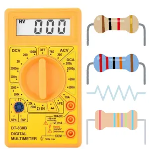
Ohmmeter
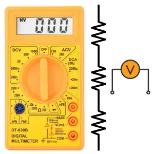
Voltmeter
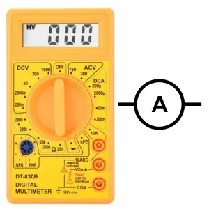
Ammeter
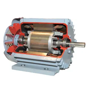
Induction Motor
Transformer
Operational Amplifiers
Components
Symbols
Formulas
EE Notes
EE Dictionary

MCQ Quiz

Interview Q&A
Power Electronics Book
Advanced Calculator
Basic Calculator
Simulator
Videos
Q&A
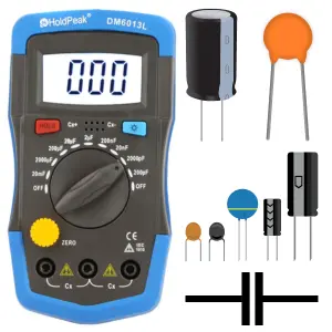
Capacitance Meter
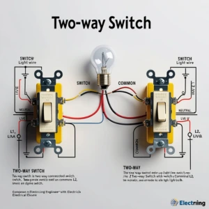
Two Way Switch
Electrical Machines
Power Electronics

Electrical Drives & Their Control

Electrical Safety & Standards

Basics of Electronics Engineering
Electromagnetic Fields
Electrical Machines

More Items Coming Soon...