2 Answers
### Basic Concept
A galvanometer works on the principle of electromagnetic induction. When an electric current flows through a coil situated in a magnetic field, it experiences a torque that causes the coil to rotate. This rotation is typically indicated on a scale by a pointer. The relationship between the current and the deflection of the pointer can be described using several key variables.
### Formula for Galvanometer Current
The current \( I_g \) flowing through the galvanometer can be related to the deflection angle \( \theta \) of the pointer, the galvanometer's constant, and the characteristics of the system.
#### Basic Formula
A common formula to express the current is:
\[
I_g = k \cdot \theta
\]
Where:
- \( I_g \) is the galvanometer current (in amperes).
- \( k \) is a constant specific to the galvanometer (often referred to as the sensitivity or calibration constant) which relates the angle of deflection to the current. This constant is usually expressed in units such as amperes per degree (A/°).
- \( \theta \) is the angular deflection of the galvanometer pointer (in degrees or radians).
### Detailed Explanation of Components
1. **Galvanometer Constant \( k \)**:
- This constant is determined by the design and construction of the galvanometer, including the number of turns in the coil, the strength of the magnetic field, and the physical dimensions of the coil. A higher value of \( k \) means that the galvanometer is more sensitive to changes in current.
2. **Deflection Angle \( \theta \)**:
- The angle of deflection is a measure of how much the needle moves in response to the current. The scale on the galvanometer allows you to read this angle. The deflection is proportional to the current flowing through the device.
### Practical Usage
When using a galvanometer in practice, you may want to convert this relationship into a more practical form to find the current in a circuit. If you have a known resistance \( R_g \) across the galvanometer and the voltage \( V \) applied, you can use Ohm’s Law:
\[
I_g = \frac{V}{R_g}
\]
In this case, you may also use the deflection angle to find the relationship with the voltage and adjust your calculations accordingly.
### Conclusion
In summary, the current through a galvanometer can be represented by the simple linear relationship \( I_g = k \cdot \theta \). Understanding this relationship allows you to interpret the readings of a galvanometer in various electrical experiments and applications. If you're measuring current directly, you can also use Ohm's Law to find current based on voltage and resistance. This knowledge is fundamental in both experimental physics and electrical engineering.
### Basic Formula
The current \( I_g \) flowing through a galvanometer can be expressed with the following formula:
\[
I_g = \frac{V}{G}
\]
Where:
- \( I_g \) = current through the galvanometer (in Amperes)
- \( V \) = voltage across the galvanometer (in Volts)
- \( G \) = galvanometer's internal resistance (in Ohms)
### Detailed Explanation
1. **Voltage (V)**: This is the potential difference applied across the galvanometer. It’s crucial because the amount of current that flows through the galvanometer is directly proportional to this voltage.
2. **Galvanometer Resistance (G)**: Each galvanometer has an internal resistance that affects how much current can flow through it. The higher the resistance, the less current will flow for a given voltage.
### Sensitivity of the Galvanometer
The sensitivity of a galvanometer is defined as the amount of current that causes a full-scale deflection of the pointer. This is often denoted as \( S \):
\[
S = \frac{I_g}{\theta}
\]
Where:
- \( S \) = sensitivity (in Amperes per degree or radians)
- \( I_g \) = current for full-scale deflection (in Amperes)
- \( \theta \) = angular deflection of the galvanometer needle (in degrees or radians)
### Relationship with Other Circuit Components
When the galvanometer is part of a larger circuit, especially in the case of using it in series or parallel with resistors, the total current can be calculated using Ohm’s law and Kirchhoff’s laws:
- **In Series**: If the galvanometer is in series with a resistor \( R \):
\[
I_{total} = \frac{V}{R + G}
\]
- **In Parallel**: If the galvanometer is in parallel with another component, the voltage across the galvanometer is equal to the voltage across that component, and you can find \( I_g \) using the initial formula.
### Practical Considerations
- **Calibration**: Galvanometers are often calibrated to provide direct readings in terms of current, meaning that the deflection can be read directly as a certain amount of current. This calibration is essential for practical use.
- **Maximum Deflection**: It is important to not exceed the maximum current rating of a galvanometer to prevent damage. If the expected current is higher than the galvanometer’s capacity, a shunt resistor may be used to protect it.
### Example Calculation
**Example**: Suppose a galvanometer has a resistance of 100 Ω, and a voltage of 5V is applied across it.
\[
I_g = \frac{V}{G} = \frac{5V}{100Ω} = 0.05A = 50mA
\]
This means that a current of 50mA will flow through the galvanometer when a voltage of 5V is applied across it.
### Summary
The formula for calculating the current in a galvanometer is simple but crucial for understanding its operation. It relates the current to the voltage and resistance of the device. Understanding these concepts is fundamental for working with galvanometers in various electrical engineering applications.

Applied Physics
Signals and Systems

Digital Electronics
Basic Concepts
Basic Laws
Units
Ohmic Resistors
Capacitors and Inductors
RC Circuit
First-Order Circuits
Second-Order Circuits
Principles Of Circuit Analysis
Sinusoids and Phasors
AC Steady-State Analysis
Single Phase A.C. Circuits
Three-Phase Circuits
Resonance In Series And Parallel Circuits
Network Theorems
Thevenin's Theorem
Two-port Networks
Digital Electronics
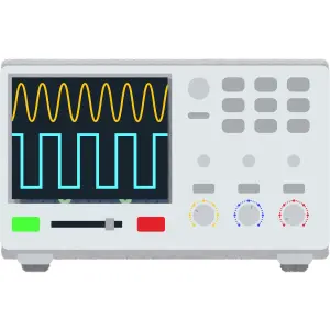
Oscilloscope
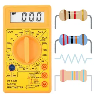
Ohmmeter
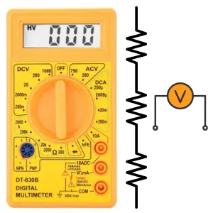
Voltmeter
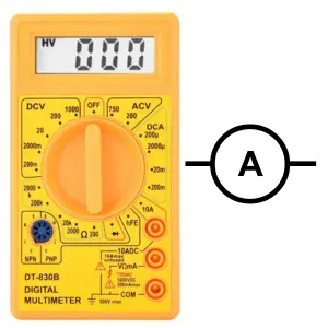
Ammeter
Induction Motor
Transformer
Operational Amplifiers
Components
Symbols
Formulas
EE Notes
EE Dictionary

MCQ Quiz

Interview Q&A
Power Electronics Book
Advanced Calculator
Basic Calculator

Simulator
Videos
Q&A
Capacitance Meter
Two Way Switch
Electrical Machines
Power Electronics

Electrical Drives & Their Control

Electrical Safety & Standards

Basics of Electronics Engineering
Electromagnetic Fields
Electrical Machines

More Items Coming Soon...